Attachment:
File comment: latest version
 flying bat animation_updated.pdf [501.71 KiB]
Downloaded 533 times
flying bat animation_updated.pdf [501.71 KiB]
Downloaded 533 times
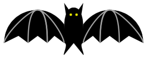
Hovering Bat
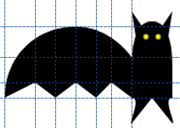
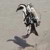
In this tutorial, I will show you how to make the following:
This general concept can be used for making other flying things.
This is not a beginner tutorial, however, I have tried to make the tutorial specific enough that new users might be able to follow along, but having a reasonable amount of experience with Gimp and GAP will help you in being able to successfully complete this tutorial.
For those of you not into animation who may be interested in learning how to make the bat, you can follow the first part of the tutorial. There are easier ways of making bats and this bat is designed with animation in mind, but again, the first half of the tutorial is learning to make just the bat. There are no animation steps involved in making the bat.
Open a new 400x400 image (File | New) and save it into a working folder of your choice. I name the image parts.xcf since it will contain all of the parts that will be used for the animation.
First we will create the base bat body.
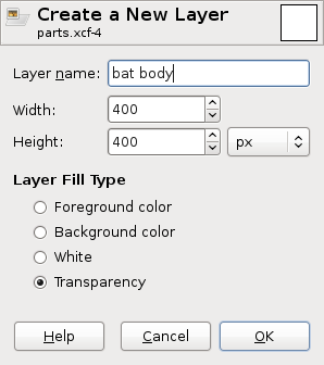
Create a new layer (Layer | New Layer) and name it: bat body
Setting Up The Guides
Place your mouse cursor over the top horizontal ruler bar and Click+Drag a horizontal guide line down until it reaches 200 on the vertical ruler on the left side. You will see a message at the bottom of your window informing you of what position your guide is at:
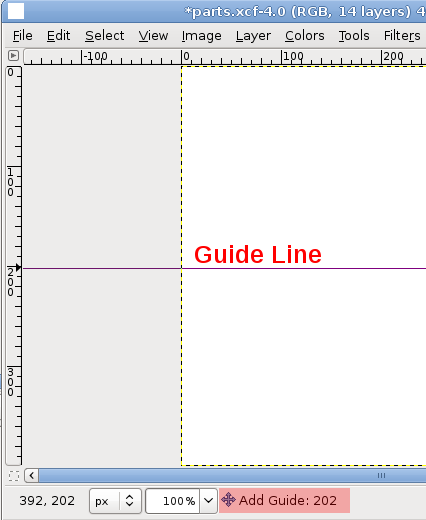
Above, the guideline is dragged down to position 202, so it will need to be dragged back up by 2 to a position of 200.
Click+Drag four more horizontal guidelines to positions 150, 185, 225, 250.
Click+Drag a vertical guideline from the vertical ruler bar on the left side of the image window until it also reaches position 200 on the horizontal ruler bar.
Click+Drag four more vertical guidelines to positions 180, 190, 210, 220.
With all guidelines in position, this is what your image window generally should look like:
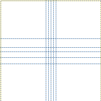
In cropping the image, the bottom of the layer boundary guide (dotted lines highlighted in yellow) was cut off, but it is there in the actual image for anyone wondering about that. This is meant just to show the placement of the guidelines. If yours is not similar to the above, then please check to make sure that you have dragged all of your guidelines to the appropriate position.
Creating the Bat Body with Paths
Select the Path Tool.
Place your mouse cursor at the point where the horizontal guide at 150 intersects the vertical guideline at 200 (that is x,y position 200,150) and add your first Anchor there:
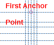
Shown above, the Anchor point is a small circle.
With the Path Tool still selected, successively add more Anchor points at the following positions, moving in a counterclockwise rotation from the starting point. (these need to be done in order):
Finally, hold down the Ctrl key and click on the original point at 200,150 to make a completed path. You should see something like this in your image window:
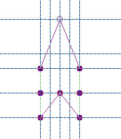
The above image is zoomed in at 200%.
For those interested in the x,y locations of the other Anchor points, after the first, in order of placement, here is the list:
180,200
180,225
180,250
200,225
220,250
220,225
220,200
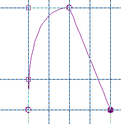
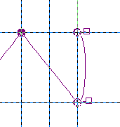
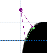
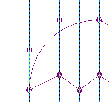
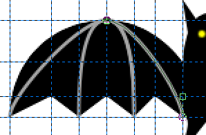
The next steps will be about adding curves to the bat body path.At this point, I would recommend zooming in on your image to a 400% zoom. With the Path Tool still selected, click and drag the upper left diagonal path line to the left until the handles of the two Anchor points it is between begin showing:
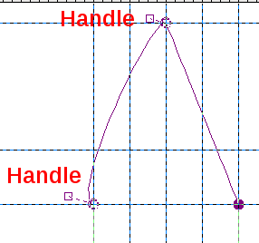
Grab the upper Anchors handle (little square box) and move it left to x,y position 180,150 which is the left outer corner where the two guidelines meet.
Grab the lower Anchors handle and move it up to where the next two guidelines meet at x,y position 180,185, which is the next guideline intersection directly above it's Anchor point:
With the Path Tool still selected, drag the upper right diagonal line slightly to the right to expose the handles of the Anchors that it is between. Then position the upper Anchor's handle at 220,150 and the lower Anchors handle at 220,185 as shown in the image below:
Next, go to the vertical path line between the bottom two Anchors on the lower left and slightly drag it out towards the left to expose those Anchors handles:
Grab the upper exposed handle and move it to the right to position 190,225. which is the guideline intersection immediately to the right of it's Anchor point. Move the lower exposed handle just down so it is right on the lower guideline:
Now go over to the vertical path line between the two bottom right hand side Anchors and drag it slightly to the right to expose those Anchors handles:
Grab the upper exposed handle and move it left to position 210,225 (guideline intersection to the left of it's Anchor point). Grab the lower Anchor's handle and move it down on to the lower guideline:
In the Paths Dialog window, click on the Path to Selection button, which is located on the bottom of that Dialog window.
Bucket Fill the selection with the color Black and then select:
Select | None
After the Bucket Fill, (with the Path outline still showing) the above is what your image should look like.
Bat Ears Path
From the top horizontal ruler bar, drag down two guidelines to positions 140 and 165.
Select the Path Tool.
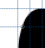
Add an Anchor point at the spot where the curved outline on the upper left side of the bat body intersects with the horizontal guideline at position 165:
Add another Anchor point at position 180,140.
Then add an Anchor point at the position where the vertical guideline at 190 intersects the curved outline on the upper left side of the bat body.
Finally, holding down the Ctrl key, click on the first path point shown in the image above to complete the path:
In the Paths Dialog window, again click on the Path to Selection button at the bottom of that window and Bucket Fill the Selection with Color Black.
Select the Flip Tool.
In the Flip Tools Tool Options Dialog window, for Affect type click on Selection. Set the Flip Type to Horizontal.
Then place your mouse cursor inside the image window and click once. The triangular selection should now be on the right side of the window.
Bucket Fill that selection with the color Black.
Then select:
Select | None
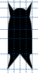
Your image should look like the above if all went well to this point.
Select the Paintbrush tool, set the Foreground Color to yellow (ffff00), and select the 7x7 Circle 05 brush and place two dots along horizontal guideline 165, one to the left of vertical guideline 200 and one to the right:
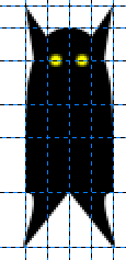
The basic bat body is complete.
Get rid of all of the guidelines before we move to the next phase of creating the bat wing paths by selecting:
Image | Guides | Remove All Guides
Bat Wing Path
Make a New Layer (Layer | New Layer) and name it Left Bat Wing.
Drag vertical guidelines from the left vertical ruler bar to positions 55, 85, 105, 125, 145, 160, and 180.
Drag horizontal guidelines down from the top ruler bar to positions 155, 185, 210, and 225.
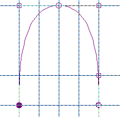
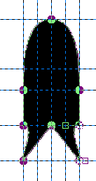
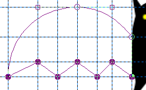
Select the Path Tool and place Anchor points at the guideline intersection positions as they are shown below. Start by placing the top Anchor and then moving in a Clockwise rotation to place the other Anchors.
After placing the final Anchor, hold down the Ctrl key and click back on the first Anchor that you placed to complete the path:
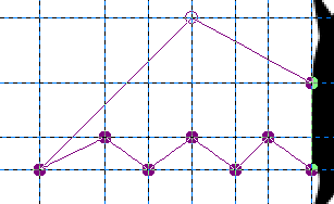
Below are the x,y positions for each Anchor in the above closed Path.
180,185
125,155
55,225
85,210
105,225
125,210
145,225
160,210
180,225
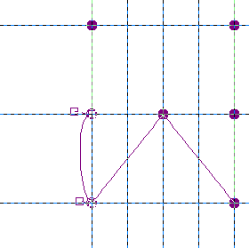
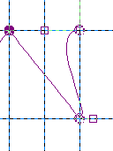
Next to be done is adding the curves to the top two diagonal path lines.
Using the Path Tool, drag the top left diagonal Path line slightly to the left to expose the handles of the Anchors that it lies between.
Move the upper handle to x,y position 85,155, which is two guideline intersections to the left of it's Anchor position.
Move the lower Anchor handle to position 55,185, two guideline intersection positions up from it's Anchor position:
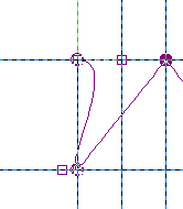
Then, still using the Path Tool, grab the upper right diagonal line and drag it slightly to the right to expose the handles of the Anchors that it lies between.
Drag the upper Anchor's handle to x,y position 160,155, two guideline intersections to the right of it's Anchor point, and take the lower Anchor's handle and place it right back on it's Anchor at position of 180,185. The left bat wing outline is now complete:
In the Paths Dialog Window, click on the Path to Selection button.
Click on the Bucket Fill Tool and fill the selection with the Color Black.
Then select:
Select | None
This should be your progress so far.
Wing Limb Path
Set the Foreground Color to a5a5a5
Select the Path Tool.
Place an Anchor at x,y position 125,155 and another at position 55,225.
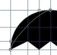
Drag the Path line between the two Anchors to the left to expose the handles of the Anchors.
Move the upper Anchor handle to 105,155, which is one guideline intersection to the left of it's Anchor position. Move the lower Anchor handle to 55,210, which is one guideline intersection above it's Anchor position:
In the Paths Dialog window, click on the Stroke Path button.
In the Stroke Path Dialog window that opens, choose Stroke Line and use a Line Width of 2.5.
Using the Path Tool, place another Anchor at the guideline intersection just to the right of the lower left Anchor.
Then in the Tool Options Dialog for the Path Tool, switch Edit Mode from Design to Edit.
Hold down the Shift key while clicking on that Anchor just added and delete that Anchor. Then switch Edit Mode back to Design.
Now, move the lower Anchor point at 55, 225 to 105,225, which would be two guideline intersections to the right of where it currently is positioned.
Stroke the Path again with a Line Width of 2.5.
Move the lower Anchor to position from 105,225 to 145,225 (again, two guideline intersections to the right of where the Anchor currently is). Then click on the upper Anchor and move it's handle (not the Anchor, just it's handle) over to point 145,155 (one guideline intersection to the right of it's Anchor position).
Stroke the Path as above.
Finally, move the lower Anchor point to position 180,225, which is two guideline intersections to the right of it's current position.
Stroke it once again. This should be the result thus far for the bat wing.
In the Layers Dialog Window, duplicate the Left Bat Wing Layer. Rename it Right Bat Wing.
With the Right Bat Wing Layer selected, select the Flip Tool.
In the Tool Options Dialog for the Flip Tool, set the Affect to Layer and the Flip Type to Horizontal.
Place your mouse cursor inside the image window and click once.
You can again remove all of the Guidelines by selecting:
Image | Guides | Remove All Guides
Congratulations, you have just completed all parts of the bat that will be needed for the animated flying bat.
This should be your progress so far:
Animating The Bat
Your parts.xcf image window should consist of four layers. The Background, bat body, Left Bat Wing, and Right Bat Wing.
Leaving parts.xcf opened, open a new 400x400 image file (File | New).
Name it background_000001.xcf. All operations setting up the animation will now be done from the background_000001.xcf image window. Still, keep the parts.xcf window open, but you can minimize it if you wish.
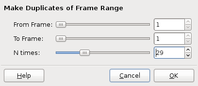
From the background_000001.xcf image window, select:
Video | Duplicate Frames
Set N times to a value of 29.
Click OK:
Select Video | Move Path
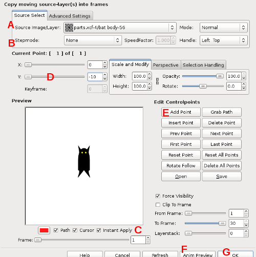
1.) Set the Source Image/Layer to the bat body layer (A)
2.) Stepmode (B) must be set to None
3.) Activate ( C ) Instant Apply
4.) Change the Y Slider Value (D) to -10 (minus 10)
5.) Click on the Add Point Button (E)
6.) Change the Y Slider Value (D) to 10 (positive 10}
7.) Click the Add Point Button (E) again
8.) Change the Y Slider Value (D) to -10 (minus 10)
9.) Click on the Anim Preview button (F) to preview the bat body animation. In the window that opens, select Exact Object on Frames. Select 10 as the Framerate. The bat body should simply move up and down after being rendered. Once you view the preview animation, close out the animation preview, and close the small multi-layered image file that gets created during the preview and select:
10.) Don't Save
11.) Click OK (G) in the Move Path window.
After GAP finishes rendering, select:
Video | Move Path
When the Move Path Dialog window opens this time, for Source Image/Layer (A) select the Left Bat Wing layer.
Follow steps 2 through 11 the same as above. This time the preview will show the bat body and left bat wing moving up and down.
After finishing step 11, once GAP finishes rendering, again select:
Video | Move Path
This time for Source Image/Layer (A) select the Right Bat Wing Layer.
Again, follow steps 2 through 11, just like previously. This time, the animation preview will show the entire bat moving up and down. All that is left is to get the wings to flap back and forth and the animation will be complete.
Select Video | Frames Modify
In the Frames Modify Dialog window, click on the Function button in the upper left corner of the window and select:
Apply Filter on Layer(s)
Leave the From Frame value at 1.
Set the To Frame value to 15.
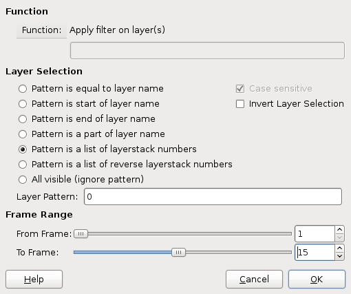
Click OK.
From the Select Filter Dialog window that opens, select plug-in-map-object and click on the Apply Varying Button:
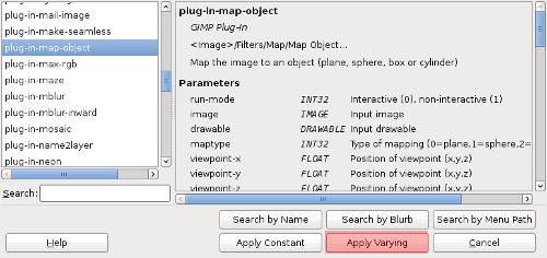
The Map Object window will open:
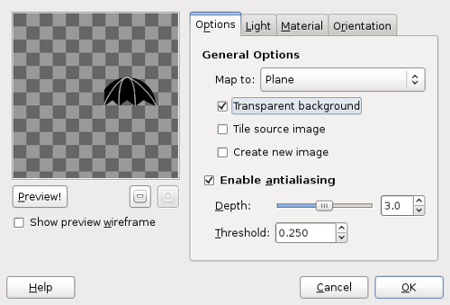
In the Options tab, Map To can be left at Plane.
Activate Transparent Background.
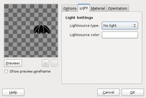
In the Light tab, shown above, set Lightsource type to No Light.
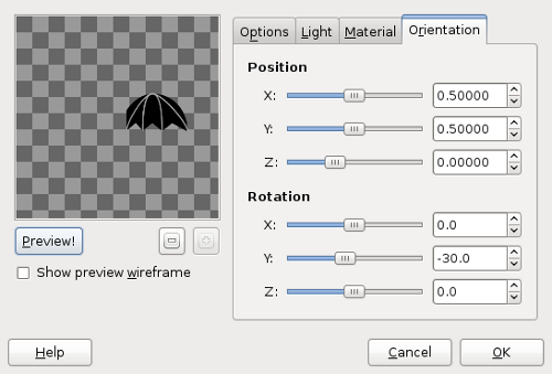
In the Orientation tab, set the Y Rotation value at -30.0 (minus 30)
Click OK.
Click Continue on the little Animated Filter Apply window that opens.
A second instance of Map Object will now open. Leave all settings the same, except go to the Orientation tab and change the Y Rotation value to 30.0, then click OK
Again, click Continue on the Animated Filter Apply window that opens.
When GAP is finished rendering select:
Video | Frames Modify
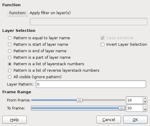
Again, click on the Function button and select Apply Filter on Layer(s)
Set From Frame to 16, and leave To Frame set at 30.
Click OK.
The Select Filter Dialog window opens.
Select the plug-in-map-object and Click the Apply Varying Button
The Map Object Window will open. Leave all settings the same except in the Orientation tab. Set the Y Rotation value to 30.0.
Click OK.
Click Continue in the small window that opens.
Map Object opens again. Change the Y Rotation value in the Orientation tab to -30.0 (minus 30.0).
Click OK.
Click the Continue button in the small window that opens. GAP will render the completion of the right wing flap cycle.
If you like select Video | Playback to watch the animation showing the right wing flap cycle now complete. Afterwards close the Playback window. We now just must complete the left wing flap cycle.
Select Video | Frames Modify
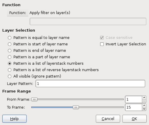
Again, click on the Function button and select Apply Filter on Layer(s)
For Layer Pattern, change it to a value of 1 (the number one). This is because we will be now working on the Left Bat Wing layer, which is at layerstack number one on each frame.
From Frame is set to 1.
To Frame, set to 15.
Click OK.
The Select Filter Dialog window opens, and from it again select:
plug-in-map-object
Click on the Apply Varying Button
Map Object opens. Leave all settings alone except for in the Orientation tab. Change the Y Rotation value to 30.0.
Click OK.
Click Continue in the small window that opens.
Map Object opens again. This time change the Y Rotation value in the Orientation tab to -30.0 (minus 30.0)
Click OK
Click Continue in the small window that opens.
GAP will render the first half of the left wing flap cycle.
When GAP is done rendering, select:
Video | Frames Modify
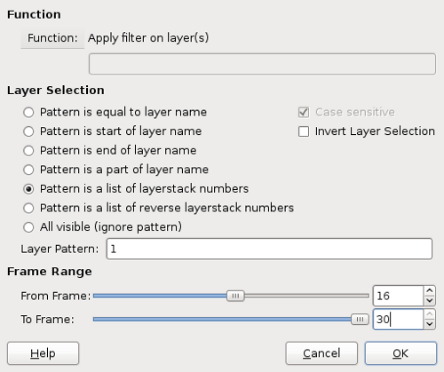
As shown in the image above:
Click the Function Button and select Apply Filter on Layer(s).
For the Layer Pattern value, change it to 1.
Set the From Frame to 16.
Leave the To Frame value at 30.
Click OK.
The Select Filter Dialog window opens.
Select plug-in-map-object and click the Apply Varying Button.
Map Object opens. Go to the Orientation tab and set the Y Rotation value to -30.0 (minus 30.0)
Click OK.
Click the Continue button in the small window that opens.
Map Object opens again. This time in the Orientation tab, set the Y Rotation value to 30.0
Click OK.
Click the Continue Button in the small window that opens.
When GAP finishes rendering, select:
Video | Frames To Image
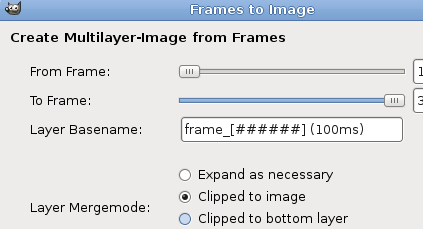
Leave all settings at default except for the timing value in Layer Basename. By default it is set at 41ms. Change that value to 100ms. Click OK
A new image with 30 layers will be created. Go to the Layers Dialog window and delete frame_000030 and frame_000015. Those two frames stop the motion of the bat. Removing them allows the bat to appear to hover smoothly.
At this point, you may choose to save the file as an animated GIF. Since this image uses only a very few colors, optimizing it to make a smaller file size makes sense. So the next step is to select:
Filters | Animation | Optimize (for GIF)
This will create yet another new multi-layer image file. You can close out the previous multi-layered one and select Don't Save.
From this new one, you can now save it as hovering_bat.gif or whatever name you choose, just make sure that the .gif suffix is at the end of the file name.
The Export Dialog Window will open:
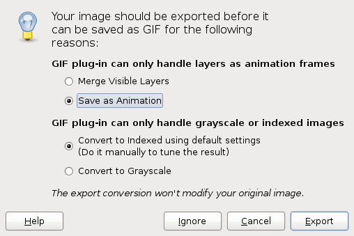
Make sure to select Save As Animation in the Export Dialog window. Otherwise, all of your layers will be flattened into one.
Click the Export Button.
In the next window that opens, just accept the default options and click Save.
Congratulations you have successfully made your hovering bat.
If you find any errors in the tutorial, I will appreciate you informing me about them.
Thank you for checking out the tutorial. PDF is attached for those wishing to save a copy of the tutorial.
Thank you for checking out the tutorial.


 for sharing your hard work.