Here is the animation:
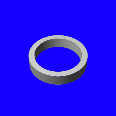
Not an exciting animation, but interesting for Gimp since it is not a 3D program and making a solid ring that is also animated is quite an involved process. While it appears as one continuous animation, it was made of 60 frames, each with 6 layers. Five of the layers of each frame are animated by multiple applications of Map Object. Additionally, some of the layers switch their positions during the animation to give the appearance of a single continuous animation.
Making something like this with Blender can be done in a matter of minutes. Doing it with Gimp and GAP took hours of planning, setup, and rendering. The challenge is how far one can push Gimp and GAP to make things it wasn't generally designed for.
Background (for the curious):
First, I wondered how I could use Map Object to make a solid ring object. Normally, if you use Map Object to make a Cylinder object and use hollow rings for the top and bottom caps, a cylinder will be created, but it will have no thickness to it's walls. Providing that thickness was the original goal. I did that by making two layers. Once rendered, each of those layers would become the front and back of the cylinder. A third layer was a hollow ring pattern, which I used for the top and bottom caps of the cylinder. I then set up a fourth layer to be rendered as the back inner wall of the cylinder. I rendered that cylinder layer at a smaller width from the first two cylinder layers. The width was not arbitrary in size though. Rather, I calculated what size my top and bottom cap rings had to be and what width factor I would have to use on Map Object to make the smaller "inner wall" of the cylinder match up with the inner portion of those rings.
[
Geek alert 

]
To make the math specific, I started with a 400x400px image. I made the ring caps outer diameter 400x400. Since the width factor for Map Object for a cylinder object is 0.25, that meant that if I must made a cylinder from a 400x400 filled layer, once it was rotated properly, it would make a cylinder whose outside diameter was 100x100 if the Length factor is set to 0. (400 X 0.25 = 100) The reason the Length factor is set to 0 for the calculations is because this gives us the center cross section of the cylinder. If we have a cylinder whose length factor is 1 for instance, then the diameter of the cap facing closest to us, will appear larger than it actually is, while the diameter of the opposite cap furthest from us will appear smaller. The true size of the cylinder diameter is located at the center slice. This is at Length factor of zero (0). I never set the Length factor to zero (in fact I used a Length of 0.10 for this experiment), I just keep that in mind for the calculations. I set the inner diameter of the ring caps at 320x320. Multiplying 320 by the Map Object width factor of 0.25 equals a value of 80. So 80 would need to be the diameter of the inner wall of the cylinder, to match with the inner diameter of the cylinder caps (at Length factor 0). Since the image was 400x400, getting a value of 80 for a final result required a Map Object width factor of 0.20 (80/400=1/5=0.20) So the inner cylinder wall would be made from a cylinder whose width factor was 0.20. This may be a little confusing, but behind all computer graphics applications is math. The math used for this purpose is simple compared to much of the math applied behind the scenes in Gimp (and GAP).
[
/Geek alert]
In order to highlight the 3D effect of the results, I decided to rotate the composite object 45 degrees about the X-axis coordinate, resulting in this:

I then figured out how to rotate it 90 degrees in the opposite direction to get this:

I then started manipulating the rings and applying a few filters coming up with this:

After all of that, I then decided to take the plunge and attempt to animate it. I didn't animate it going a full 360 degree flip, since that would have required more layers and more shuffling of layers during the animation for it to work. Again, the result is rather plain, but doing something like this, really gave me an appreciation for what ultimately goes into a 3D application like Blender, just to make a simple animation. Also, it's a test of just how far Gimp and GAP can be pushed.
Thank you for checking this all out.

P.S.: I have added two XCF files, one an XCF file of a tilted ring, showing the various layers used in making the ring. The other one named used_parts.xcf are the parts used to make the various parts of the animation (with the exception of the background, but that is trivial to add).


