Metal Wurx – Part XXIII
How to Make a Control Lever
We are nearing the end of the Metal Wurx series but first I wanted to share the creation of this Control Lever. This tutorial doesn’t require a great deal of skill and has been created using Gimp version 2.6.11. If you have Version 2.8, very little will be different. You will however, need to have Python installed as well as a few other things.
First of all you will need the Selection Bevel script available here:
http://gimpscripts.com/2011/10/selection-bevel/ .
You will also need Rod’s steel pencil gradient, a Phillips Screw head brush and some brushed metal all of which are included in the Resources zip file attached along with a PDF of this tutorial. Here’s what we’re going to make.

I have provided a ton of screenshots to help make this easier because it is a long and complex tutorial made for intermediate level skills. Even though you may find this challenging, I’m sure you can handle it!
Step 1.
Open a new layer 400 pixels wide by 600 pixels high. Use a resolution of 300.
Step 2.
Increase your view setting to 400% and place a Vertical guide at 200 pixels and a Horizontal guide at 300 pixels.

Step 3.
Open the Brushed Metal image provided or use your own if you like. Right click on the image layer in the layer stack and select Layer to Image Size Now right click again and select Add Alpha Channel. Rename this layer to “Base Plate”.

Step 4.
Click on the Rectangle Select tool and in the tool dialog check the boxes for Rounded corners and Expand from center. When you click on the Rounded corners a Radius setting will appear. Move the slider or just enter 35 for the value.
With your view setting still at 400%, place your cursor exactly in the center at the intersection of the two guides and drag out as far as you can in your image window.
Adjust your view setting back to 100% and adjust the size of your selection to 300 pixels wide and 400 pixels high like in the screenshot below.

Step 5.
Go to Select>Invert then make sure the Base Plate layer is the active layer and hit your delete key to remove everything outside the selection.

Go to Select>None to turn off the selection.
Step 6.
Place a horizontal guide at 50 pixels. Select the Move tool and in the tool dialog, make sure to tick the button for “Move the active layer”. Increase you view to 200% and when you click on the image in the image window you will see a plus sign appear in the very center of the image as long as you hold down the left mouse button. Move the Base Plate layer up until the top edge aligns with the new horizontal guide we just made and make sure to keep the plus sign centered on the vertical guide. Use your keyboard arrows to make any fine adjustments as necessary.

Step 7.
Let’s place a few more guides while our view is still at 200%. Place a vertical guide at 85 pixels and another one at 315 pixels. Place a horizontal guide at 85 pixels and another one at 415 pixels. If you need to adjust any of the guides after you have placed them, tick the circle in the Move tool dialog for “Pick a layer or guide” then reset it back to “Move the active layer” after you are finished. These guides will serve as locations for our base plate mounting screws.

Select the Brush tool and in the tool dialog select the Phillips Screw Head brush, set the Scale to .15, and create a new transparent layer named “Screws”. Use the paintbrush tool to carefully place a screw head at the intersections of the additional guides in the four corners, then reduce your view back to 100%.

Step 8.
Our screws are a bit too dark so go to Colors>Curves and adjust the center of the curve up about one square as shown below, then click OK.

Step 9.
Right click on the Screws layer and select Alpha to Selection. Go to Select>Shrink and enter 3 for the amount, then click OK. Now click on the Base Plate layer to make it active, then hit the delete key. Turn off the visibility of the Screws layer and you will see that we just made four small holes in the corners of our Base Plate. You’ll understand why we made the holes smaller than the screws in a moment. Go to Select>None to turn off the selection.

Step 10.
Click on the Rectangle Select tool again and this time set the Rounded corners Radius to 50. Place your cursor on the center vertical guide in about the center of the Base Plate and drag out to make a selection 60 pixels wide and 332 pixels high. Use your keyboard arrows to move it up or down until the top and bottom of the selection align with the top and bottom horizontal screw guides.

Now hit your Delete key to cut out the selected area from the Base Plate, then go to Select> None to turn off the selection.

Step 11.
Right click on the Base Plate layer and select Alpha to Selection. Go to Filters>Distorts>
Bevel (this is the Python based Selection Bevel filter you just installed.) and enter the settings shown below.

Make sure that Grain Merge is selected at the top for the Layer Mode. When you have entered and double-checked all the settings and are satisfied, click OK to initialize the filter.

When the filter has completed, go to Select>None to turn off the selection. Turn on the visibility of the Screws layer and you will see that the smaller holes we made, as well as bevel settings we used, give us a nice indentation around our screws as well as a bevel to our Base Plate.
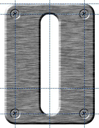
Step 12.
Right click on the Bevel layer made by the filter and select Merge Down. Next, click on the Screws layer to make it active and go to Filters>Light and shadow>Drop Shadow and apply these settings. Since the screws are so small we only want a very slight shadow.


If you zoom in about 400% and look closely at the screws, you will see a slight highlight on the top left edge. Since these screws are countersunk into the Base Plate, they should actually have a slight shadow instead.

Step 13.
Right click on the Screws layer and choose Alpha to Selection. Create a new transparent layer above the Screws layer and name it “Screw Shadows”. Now drag your FG color (Black 000000) over to the selection to fill them. This will give us four small black circles where our screws are located.

Select the Move tool and click on one of the selections to activate the tool. Use your keyboard arrows to move the Screw Shadows layer up 2 pixels and left 2 pixels. Now hit the delete key to remove most of the black circle areas leaving only a small crescent shape for each one.
It will be hard to see even at 400% so turn off the visibility of the Base Plate layer and the Drop Shadow layer so we can see what we are doing.

Step 14.
Go to Filters>Blur>Gaussian Blur and enter 3 for both amounts and click OK. Click on the image window one time to activate the Move tool (should already be selected) and use the keyboard arrows again to move the crescent shaped shadow down 1 pixel and
right 1 pixel. Now turn on the visibility of the Base Plate and the Drop Shadow layers and you will see the result.

Now, that’s more like it.
Step 15.
We still have one last thing to do to complete our Base Plate. Turn off the visibility of the Background layer and make sure the visibility of all the other layers is turned on. Right click anywhere in the layer dialog, select Merge Visible Layers, then adjust your view setting to 100%. You should now be back to only two layers.

Right click on the Base Plate layer and select Alpha to Selection. Create a new transparent layer above it named Gradient. Set the layer Mode to Grain Merge and the Opacity to 70%. Next, select the Blend tool and in the tool dialog, click on the sample Gradient and when the list pops up, scroll down to the Steel_Pencil_RD gradient and select it. Be sure to check the box next to the gradient to reverse it. Place your cursor at the very top left corner of the whole image and stroke down diagonally to the third horizontal guide and at the very outside edge of the image as shown in the image below.

This gives our metal some sheen and completes the Base Plate. Right click on the Gradient layer and select Merge Down.
Step 16.
Go get the Rectangle Select tool and in the tool dialog uncheck the boxes for “Rounded corners” and “Expand from center”.
Create a new transparent layer above the Background layer and name it “Slot Background”.
Make a selection just a little bit bigger than the size of the slot and drag your black Foreground color over to the selection to fill it.

Go to Select>None to turn off the selection.
Step 17.
Create a new transparent layer above the Base Plate layer and name it “Shaft” and increase your view setting to 150 to 200%. Make a selection about 2 pixels inside the slot on both sides, and from about the middle of the slot down to a point halfway between the bottom of the Base Plate and the bottom of the whole image.

Select the Blend tool and with the same gradient as before, leaving it reversed and stroke horizontally from the left side of the selection to the right side to apply the gradient, then go to Select>None to turn off the selection.
Our image now looks like this.

Step 18.
You will need to increase your view setting to 800% for this step. Click on the Ellipse Select tool and make a selection at the bottom of the shaft the exact same width as the shaft (should be 56 pixels) and about 18 pixels high. Use your keyboard arrows to move it into position so that the bottom of the selection is even with the bottom of the shaft.
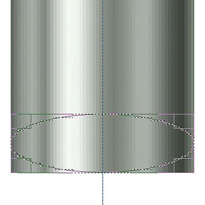
Go to Select>Invert, then select the Eraser tool. In the tool dialog, select the Circle (15) brush and set the Scale to about 7. Carefully erase around the bottom edges of the selection to help make the shaft look more rounded. Go to Select>None to turn off the selection.

Step 19.
Change your view setting back to 150% and right click on the shaft layer to choose Alpha to Selection. Go to Layer>Crop to Selection then Select>None to turn off the selection. I use this technique quite often to get a more manageable layer size for procedures similar to the one that follows.
Place a horizontal guide at 250 pixels. Next, select the Perspective tool and click on your image to activate the tool. You will see a small square appear at each corner of the layer.
We will use these like “handles” to reshape the layer.
Starting at the top left corner, left click on the little square and hold down the mouse button to carefully “drag” it down to the new guide and then about 4 pixels to the right. Now “grab” the top right corner by holding down the left mouse button again, and drag it down to the guide and this time to the left about 4 pixels.

The two bottom corners we just need to move out 4 pixels on each side to make the bottom of the shaft wider. If you mess this up don’t worry about it, just wear out the old Reset button in the tool dialog and keep trying until you get it to look right. When you’re done, click on the “Transform” button in the Perspective dialog.

Step 20.
Create a new layer above the Shaft layer and name it “Shaft Shadow”. Select the Paintbrush tool and select the largest Fuzzy brush and set the Scale all the way up to 10.
Move the pointer to the top left corner of the shaft and click repeatedly until the top edge of the shaft disappears. Zoom in at 400% and watch as you “paint” to make sure the top edge gets completely covered by the painted in shadow. You may still need to reduce the size of your brush and paint over the very top edge to get it completely covered up.

Right click on the Shaft layer and choose Alpha to Selection then go to Select>Invert. Next, right click on the Shaft Shadow layer and select Layer to Image Size. Now, hit your Delete key to remove the part of the shadow outside the selection. Turn off the selection (Select>None), then right click on the Shaft Shadow layer and select Merge Down. Right click on the Base Plate layer, select Merge Down, and rename it back to Base Plate. The Shaft portion of our Control Lever is now complete.

Step 21.
Go to Image>Guides>Remove all Guides, then create a new transparent layer above the Base Plate layer and name it “Handle”. Increase your view to 400% and place a single Vertical guide in the center again at 200 pixels. Adjust your view back down to about 200% and click on the Rectangle Select tool again. Uncheck everything in the tool dialog except “Expand from center”. Place your cursor on the vertical guide where it intersects with the very bottom edge of the shaft. Drag out until the selection is 140 pixels wide and 70 pixels high.

Step 22.
Select the Blend tool and use the reversed Steel_Pencil_RD gradient again, but this time stroke from the top of the selection to the bottom, using the control key to get it perfectly vertical. Once you have applied the gradient, go to Select>None to turn off the selection.
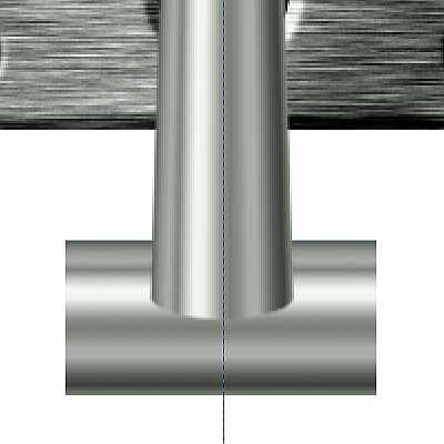
Step 23.
Select the Move tool and click on the image window once to activate the tool. Use the Down arrow key on your keyboard to move the handle down until the top edge is even with where the rounded bottom part of the shaft starts like this.
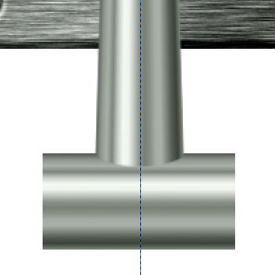
Step 24.
Create a new transparent layer above the Base Plate layer and call it “Ends”. Change your view setting at 800% and use your scroll bars to move to the left side of the handle. Click on the Rectangle Select tool and check the box for “Rounded corners” and uncheck the box for “Expand from center”. The default Radius is set to 5 for the rounded corners and we’ll just use that setting. Make a selection 40 pixels wide and 64 pixels high. Position the selection using the keyboard arrows so that the rounded corners on the right side of the selection are inside the left end of the handle and centered vertically as shown below.
Tip: Make the left edge of the corner squares even with the end of the handle (or even a little more) to get all of the radius inside.

Change your FG color to Red (FF0000) and drag it over to the selection to fill it. Go to Select>None to turn off the selection then Select>None to turn off the selection. Right click on the Handle layer and choose Alpha to Selection. Reselect the Ends layer and hit your Delete key to remove the part that overlaps “underneath the Handle layer, then turn off the selection. Change your view setting to 400% and here’s what we have now.

Step 25.
Duplicate the Ends layer and go to Layer>Transform>Flip Horizontally. Move your scroll bar to the right so you can see the right end of the handle. The Ends copy layer should be in position already or almost depending on the positioning of the original Ends layer. If not, select the Move tool and click on the image to activate the tool then use your arrow buttons on your keyboard to position it until it lines up exactly with the right edge of the handle and centered vertically.

Right click on the Ends copy layer and select Merge Down. Move the Ends layer up above the Handle layer. Now, right click on the Ends layer and select Merge down. (this way we don’t have to rename the layer)
Step 26.
This step is optional but I use this step to dress up the ends a little more. Create a new transparent layer above the Handle layer and name it “Ends 2”. Basically we’ll be repeating the procedures outlined in Steps 23 and 24 except we want our selection to be very small in width like 8 or 10 pixels, and about 6 pixels smaller in height so that the selection starts where the rounded corners of the ends stops. Set the Radius of the corners on the selection to 3 and position it as shown below.

Fill the selection with red then turn off the selection. Right click on the Ends 2 layer and select Layer to Image Size.
Step 27.
Duplicate the Ends 2 layer, go to Layer>Transform>Flip Horizontally. You won’t be able to see it but it is there. Reduce the opacity of the Handle layer to about 50 % so you can see the Ends 2 copy layer then select the move tool and using your keyboard arrows again, position it to match the ends 2 layer on the left. Do not merge these two layers yet.
Your image and layers should now look like this.
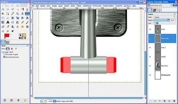
Reset the Opacity of the Handle layer back to 100% then right click on the Ends 2 copy layer and select Layer to image size.
Step 28.
Adjust your view setting to 300% and create a new transparent layer above the Ends 2 copy layer named “Gradient”. Set the layer Mode to Grain Merge. Click on the Rectangle Select tool and uncheck the box for Rounded Corners. Make a selection exactly even with the outside edges of the Ends 2 layers and the Handle layer.
Select the Blend tool and make sure the gradient is still reversed and the little box is checked. Now, drag down vertically from the top of the selection to the bottom using the Control key to get it perfectly straight and apply the gradient. This will give our handle and the ends a cylindrical look similar to the Shaft portion.

You may have already noticed that since we already have a gradient applied to the Handle layer and it is underneath this gradient, it appears brighter than the Shaft layer. Let’s go ahead and correct this now.
Step 29.
Zoom in to 400%. Use your Rectangle Select tool again and, on the Gradient layer, click on the middle of the selection to get the squares at the corners again. Adjust the left and right sides of our selection until it is exactly on the edges of the Metallic (center) portion of the handle (the part that’s too bright) and Hit the Delete key to remove the additional gradient from this area. Go to Select>None to turn off the selection.
Step 30.
Right click on the Handle Layer and select Alpha to Selection. Now select the Ends 2 layer and hit your Delete key to remove the excess. Now, select the Ends 2 copy layer and hit your Delete key. Now our layers don’t overlap.We still have a bit more clean-up to do but first we need to make a couple of adjustments.
Step 31.
Create a new transparent layer above the Ends 2 layer named “Highlight” and set the layer Mode to Grain Merge and the Opacity to 50%. Right click on the Ends 2 layer (the one on the left) and pick Alpha to Selection. Select the Blend tool and reverse the FG/BG colors so that white is the FG color and Red is the BG color.
Now change the BG color to C30000. Select the Blend tool and in the tool dialog, set the gradient to FG to BG (RGB) and “un-reverse” the gradient so that the white portion is on the left in the sample gradient. Reselect the Highlight layer to make it the active layer and drag your cursor from the top of the selection to the bottom (using the Control Key) to apply the gradient. Go to Select>None to turn off the selection.
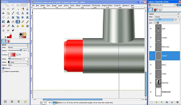
This brightens up the end just a little to help distinguish it from the rest of the end part. Right click on the Highlight layer and select Merge Down.
Step 32.
Create a new transparent layer above the Ends 2 copy layer and name it “Shadow”. Adjust the Opacity of the Shadow layer to 75% and leave the layer Mode set to Normal.
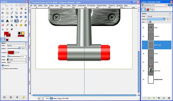
Set the FG color to 880000 then reverse the FG/BG colors so that the darker portion is on the right in the sample gradient. Right click the Ends 2 copy layer and choose Alpha to Selection, then reselect the Shadow layer to apply the gradient in the same manner as in Step 31above only this time we are darkening the selection for distinction.
Turn off the selection and adjust your view back to 200%. Right click on the Shadow layer and select Merge Down.
Step 33.
Right click on the Ends 2 copy layer and select Merge Down. Now, right click on the Ends 2 layer and select Merge Down so that we now have only one layer for the handle and the ends.
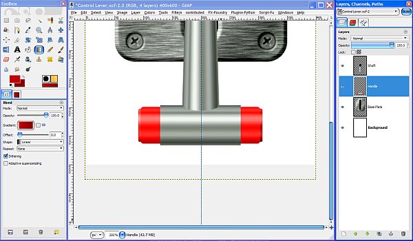
Right click on the Handle layer and select Alpha to Selection. Go to Select>Invert, then select the Gradient layer to make it active. Hit your delete key to remove the excess Gradient layer and that finishes up the clean-up we were doing earlier.
Select>None to turn off the selection, then right click on the Gradient layer and select Merge Down.
Step 34.
The reason we kept all these layers separate is because we want to create our drop shadows separately for the Handle and the Shaft so our lever looks like it is sticking out. Reduce your view setting to 100% then select the Shaft layer and go to Filters>Light and Shadow>Drop Shadow and enter these settings. Uncheck the box for “Allow resizing”.

The resulting shadow will need a couple of adjustments to make it look right.

Step 35.
Since the shaft is supposed to be sticking out away from the surface, the shadow will need to be at an angle. Select the Rotate tool and then click on your image once to activate the tool and bring up the dialog box. Set the Angle to -10.00 and click on the Rotate button.

Once the shadow has been rotated, rename this layer to “Shaft Shadow”.

We’ll come back and make some adjustments to this in just a minute but first let’s make the other shadow.
Step 36.
Select the Handle layer and go to Filters>Light and Shadow>Drop Shadow and this time we use these values in the Drop Shadow dialog.

This will put our shadow considerably lower than the handle but centered on the Shaft Shadow. If you turn off the visibility of the Shaft and Handle layers on and off you can see both shadows together.

Step 37.
Turn on the visibility of the Shaft and Handle layers and move the Handle layer up in the layer stack between the Shaft Shadow layer and the Shaft layer. Now the Shaft Shadow appears to be underneath the handle where it is supposed to be.
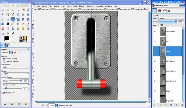
Step 38.
Select the Base Plate layer to make it active. Go to Filters>Light and Shadow and use the values in the screenshot below to give this layer a drop shadow as well. Since it is sitting right on the surface, it does not cast a very big shadow and it should be a little darker.

Remove the guide and delete the Background layer. Right click anywhere in the layers dialog to select Merge Visible layers. When the Merge dialog comes up, click on the Merge button to merge all the layers. Right click the resulting merged layer (it will now
be named Drop Shadow #1) and select Layer to Image Size and our Control Lever is pretty much complete.

There is one thing left to do land that is adjust the gradient on the bottom edge of the Handle. I probably should have done this when we were working on it back in Step 22, but it’s no problem to correct it now, besides, it’s a pretty easy fix.
Step 39.
Adjust your view back up to 550% for this step. (go to 800% then zoom out) Click on your FG color and use the color picker to select the darkest color near the bottom edge of the Handle (about 4 pixels up) then Click OK.

Whatever the color turns out to be, write down or copy the 6 digit number (hex code) and set the BG color to the same color and click OK to set it. Now click on the BG color again and this time set it just a little darker by clicking on the horizontal line just to the left of the vertical line in the dialog window.
Go get the Rectangle Select tool and make sure there are no boxes checked. Make a selection from one side of the metallic part of the handle to the other and from the bottom edge up to but not over the dark gray line which should be about 3 to 5 pixels high and 140 pixels wide.
Select the Blend tool and make sure the Gradient is set to FG to BG (RGB) and the box to the right is unchecked to “unreverse the gradient. Drag straight down from top to bottom of the selection (use the Control key to get it perfectly vertical) to apply the gradient.

Now we can say we’re actually finished! You could of course make the center metallic part of the handle slightly curved on the ends, but that would require about ten more steps so I decided to keep it as simple as possible.
Turn off the selection (Select>None), set your view back to 100%, and save your image as a .png file. Make sure when the save dialog comes up that you uncheck the box that says “Save Background Color” to preserve the transparency or you will end up with an unwanted white background anyway.

Here’s the finished image.
Here’s an example of how it might be used. This was an earlier version that was not made with quite the same quality as the one we just did.

Alternate: If you use the second (lighter) brushed metal image from the zip file, you will need to adjust the curve for the screws about 1 ½ squares to match the metal color.
Here’s another example using the lighter brushed metal and the gradient applied at a slightly different angle.

I hope you enjoyed this tutorial. Next in our Metal Wurx series is how to make a Bat Switch that we will use in our final segment.
 Login
Login Register
 Tweets
 FAQ
FAQ Advanced Search